Acquiring data
Using wollaston or not
The command to move the wollaston in/out is :
firstpl_wollaston in/out
in the shell
Rolling vs Triggered mode
The lantern can be operated in two distinct modes: rolling and triggered. Data are acquired differently in these two modes.
Rolling mode: the camera is triggered internally and nevers stops. The electronics sets the tip/tilt to a fixed position. Data are acquired using the fitslogger manually.
Triggered mode: the camera is set to external trigger, and the electronics controls the tip/tilt to move the target at each new frame acquired by the camera. Data should only be acquired using the dedicated methods in the control terminal, and not by direct interaction with the fits logger.
To change the parameters on the camera:
Change exposure time :
cam.set_tint()Check exposure time :
cam.get_tint()Change readout mode :
cam.set_readout_mode()Options:
‘FAST’ : < 500 ms
‘SLOW’ : > 500 ms
Change crop size :
cam.set_camera_modeOptions:
‘FIRSTPL’ : For the regular Photonic Lantern mode
‘FIRSTPLWFS’ : For the Wavefront sensing mode
‘FIRSTPLSMF’ : For imaging of the SMF
‘FULL’ : Full frame
Getting data in rolling mode
The rolling mode is activated using the following method:
pls.acq.set_mode_rolling(x=0,y=0,open_loop=False)
The x and y coordinates correspond to the location of the tip/tilt. Most of the time, this should be set to 0 to keep the alignement performed with the zabers. The open_loop parameter determines whether the electronics actively controls the tip/tilt to stay centered on 0 (i.e. “closed loop” regime, or open_loop = True), or completely deactivates the control loop (open_loop = True).
Once the rolling mode is active, data can be acquired by setting up the fitslogger manually. Or from command line:
pls.acq.get_images_rolling(nimages = 150, ncubes = 1, tint = 0.05, readout_mode = 'FAST')
The parameters are as follows:
nimages: Number of DITs (ideally should be a factor of the sequence length)ncubes: Number of cubes to acquiretint: Integration time of the camerareadout_mode: ‘SLOW’ or ‘FAST’
Getting data in triggered mode
To put the system in triggered mode, run:
pls.acq.set_mode_triggered()
Once the system is in triggered mode, data should be acquired only using the dedicated command:
pls.acq.get_images(nimages = 271, ncubes = 1, tint = 0.05, mod_sequence = 2, mod_scale = 40, objX = 0 , objY = 0)
The parameters are as follows:
nimages: Number of DITs (ideally should be a factor of the sequence length). Can be left blank to just be the number of modulation positionncubes: Number of cubes to acquiretint: Integration time of the cameramod_sequence: See numbers above (must be between 1 and 10)mod_scale: the radius of the modulation pattern (in mas)
The modulation patterns are defined from -1 to 1 mas and scaled using the mod_scale parameter. There are currently 10 patterns implemented:
Number 1: Fixed position at zero
Number 2: 271 points hexagonal
Number 3: 595 points hexagonal
Number 4: 144 points rectangular
Number 5: 625 points rectangular
Number 6: 37 points hexagonal
Number 7: 127 points hexagonal
Number 8: 60 points crenels
Number 9: 188 points crenels
Number 10: 10 points circle
Modulation typical scales:
Lantern modulation: Scale = 30, sampled at 16 units
Piezo modulation: Scale = 1000, using sequence number 5 (length = 25)
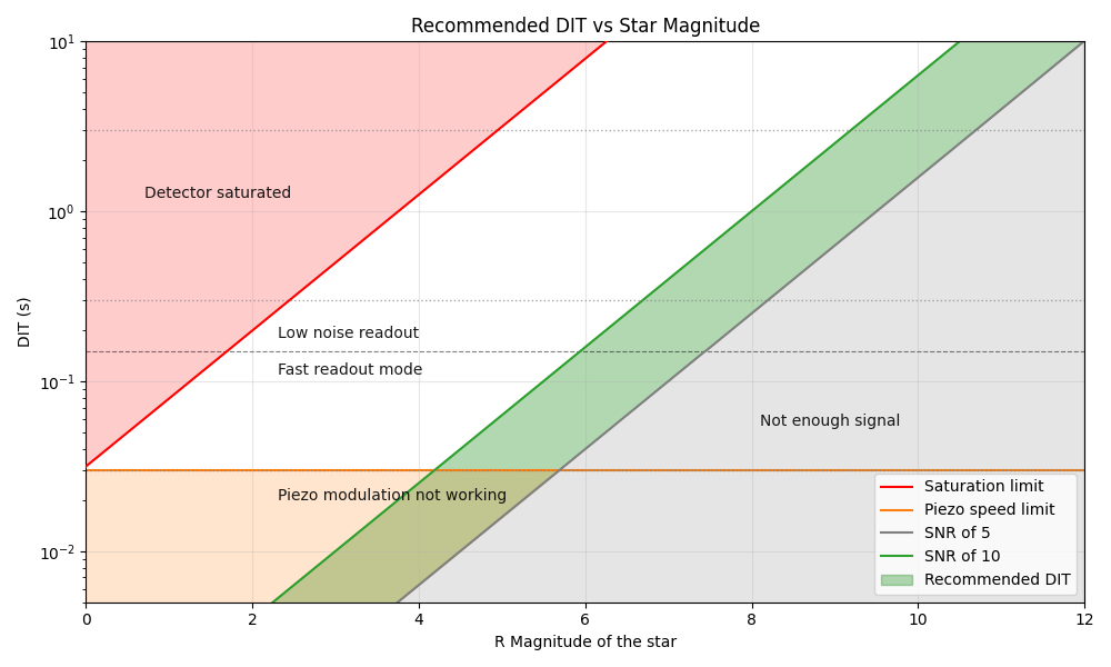
Setting the best exposure time
The detector integration time (also called exposure time) should be chosen so that we are not limited by readout noise, while keeping the integration time as short as possible. The integration time must also account for the fact that the piezo tip-tilt has a limited bandwidth of approximately 30Hz.
The easiest way is to select the detector integration time (DIT) according to the plot below:
Aligning the lantern to the source
1. Moving the photonic lantern manually with Zabers
The Zaber motors move the lantern physically in the focal plane
Commands to check and set the Zaber position:
zab.get_position(): retrieve the (x, y) position of the zaberzab.move(x, y): move the zaber to x, y absolute positionzab.delta_move(dx, dy): perform a move of dx and dy relative to current position
Note that all these commands take and return values in units of zaber steps.
2. Centering with a scan using the tip/tilt
2.1 Modulation with the Tip-Tilt
The tip/tilt mirror can be used to quickly acquire a 2D scan to locate the target and center the PL. A scan is obtained using:
pls.acq.get_acquisition_scan(wait_until_done = False, tint = 0.1, mod_scale = 200)
The mod_scale gives the size of the scan (in mas) and tint is the DIT time in seconds.
This function will return immediately. Look at the fitslogger and fitsmerger terminals to know when the scan is done and the fits file is saved.
2.2 Displaying the flux map
To display the flux from the most recent FITS file and retrieve the x, y position of the star:
x_tt,y_tt = pls.ins.opti_flux()
2.3 Centering the photonic lantern
To convert the tip/tilt x,y position retrieved from the flux map to zaber coordinates:
x_zab, y_zab = pls.geo.tt_to_zab(x_tt, y_tt)
This can be used to recenter the zaber to the correct position using a “delta_move”:
zab.delta_move(-x_zab, -y_zab)
2.4 Iterating the centering
This process can be iterated until proper centering is achieved. There is also a dedicated method to automatically perform these steps:
pls.acq.center_PL(tint = 0.1, init_scale = 200, n_iterations = 2)
Each iteration will be a zoomed iteration centered on the best position from the previous iteration. The function also takes a verification scan at the end (for a total of n_iterations+1 scans).
Tracking an off-axis target
The tip/tilt mirror can be used to observe an off-axis target. In order to do this, the electronics need to track the sky rotation, and thus need to know the local sideral time and the target cooridnates.
Synchronizing the LST
The LST on the electronics is synchronized to the computer using:
scripts.set_lstnow(location = "subaru")
This will calculate the LST at the given location using astropy, and send it to the electronics.
The electronic board does not have a proper LST clock. The LST is therefore emulated using an on-board timer, and drifts slightly. As a consequence, it is a good idea to resynchronize the LST whenever an off-axis target is observed (and not just at the beginning of the night)
Synchronizing the target coordinates
The target coordinates are synchronized between the telescope and the electronics using:
pls.acq.update_target_coordinates()
This will read the telescope pointing fro, the redis server and send them to the electronics board (using proper units and formatting).
Activate the tracking
The tracking is activated using:
ld.switch_tracking_offset(state = True)
From there on, any offset in the pls.acq.get_image command should be given in RA/DEC (in mas) and will be automatically tracked.